
I am writing this post to illustrate the path that a byte of data takes to go around the HSPA network. The details are conforming to Rel 6 of 3GPP specifications. This is just an overview, for details please refer the 3GPP specification.
The dialogue is started from the mobile device(it can be a HTTP req, email push etc), where a few bytes travel through the L3, L2 and PHY layers in the Uplink direction to reach the network nodes and routed to the application end point. There is a response from the application end point which consists of bytes destined to the Mobile(IP address).The bytes in the DL again have to go through the network nodes and the protocol layers before they reach the mobile.
Since Application end point can be any where in the internet, the start/end of the journey is from/to the GGSN on the network side.
The user starts a application such as Mobile Originated email(or HTTP req from a browsing session, ...) on the mobile, which triggers data in the Uplink. The application submits the data (as an IP packet in most cases) to the mobile modem to be transmitted in Uplink. It is assumed here that the RRC Connection and the Radio Links are already in place and the UE is in DCH state. The data is submitted under a PDP Context. A PDP Context is assigned in the GGSN where in an IP address is assigned for the connection. This connection is associated to a Radio bearer which enables the data transfer between L3 end points between mobile and network. Radio Bearer is like a service provided by the L3 to transfer data across the Air interface up to the L3 on the other end.
The modem inputs this data to the string of Radio Interface Protocols(RIP) to be packaged suitably to be transmitted over the air. Each layer of the Radio Interface Protocol plays a role in efficient and reliable transfer of the data across the Air Interface. The unit of data entering a layer is called the Service Data Unit(SDU) and after processing the unit of data exiting the layer is the Packet Data Unit(PDU). So the PDU of a upper layer becomes the SDU of the lower layer as the data traverses the RIP. The figure below shows the architecture of the RIP.

The first station in this packaging is the PDPC layer. Packet Data Convergence Protocol(PDCP) compresses the IP header in the packet. This enables more efficient use of the radio resources by eliminating some of the redundant information in the IP header(20 bytes for IPv4). This is all the more effective in case of streaming or file transfer where the packets travel between two fixed end points(IP addresses). PDCP compresses the header, attaches a header of its own(containing information about the algorithm and a sequence number of the PDU). The PDCP PDU is sent to the RLC.
Radio Link Control(RLC) layer maps the data from the Radio bearers onto the Logical Channels. The RLC does the segmentation/concatenation of RLC SDUs, ciphers and deciphers the data on RLC AM and UM mode, and provides for re transmission of the PDUs which were NACKed. Depending upon the logical channel type required, a RLC entity is setup(TM, UM or AM). Bidirectional logical channels which require reliable transfer are setup with a AM RLC entity. TM is for real time applications (like voice call), which donot require re transmission and there is no overhead of RLC header(transparent). There are not many applications which utilise the UM mode. The IP packet could be segmented depending on the RLC PDU size configured for the RLC AM entity, in which case the IP packet will be carried in multiple RLC PDUs. These RLC PDU(s) are forwarded to the MAC layer on Logical Channels.
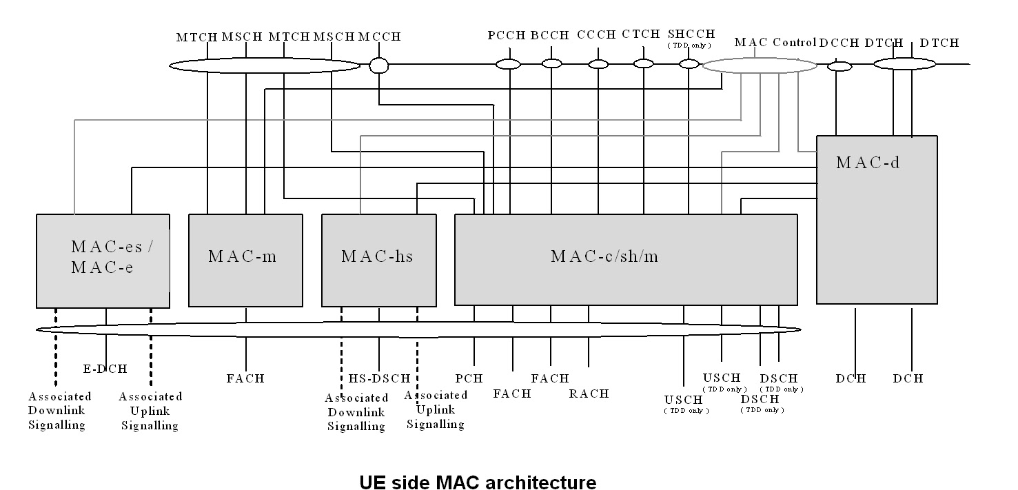
Medium Access Control(MAC) is the Link layer protocol. In Rel 6, the MAC layer is composed of MAC-e(on UE and NodeB), MAC-d(on UE and NodeB) and MAC-es(on RNC) in the Uplink direction(other MAC entities can also be present depending on configuration and transport channel to be used). The MAC plays many important roles in the reliable and efficient data transmission. It maps logical channels to transport channels, selects transport format for the transmission in each TTI, schedules the data according as the logical channel priority, among other functions.In this case the transport channel is the E-DCH Channel. The IP packet which started as part of an email from the mobile user, and has been delivered to MAC in form of RLC PDU(s) is now resting in MAC priority queues, waiting for Uplink resources (Scheduling Grants) to be scheduled for transfer on a transport block. When the moment arrives(the logical channel is scheduled), the RLC PDU(s) and formed into a MAC-e PDU to be delivered to the Physical Layer. Here again the RLC PDUs could be segmented to fit into a MAC-e PDU or several RLC PDUs could be concatenated to form a MAC-e PDU.
The UE side MAC architecture is illustrate in the figure below:
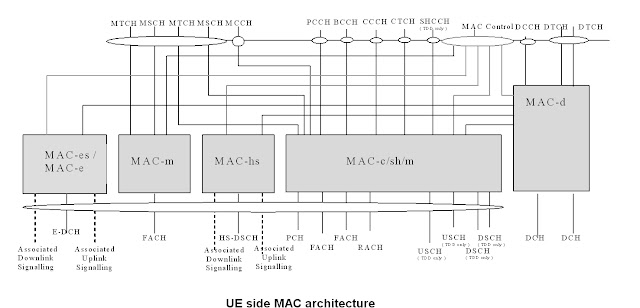
The Physical Layer(PHY) maps the transport channels onto Phycical channels. In this case the Physical channel is the E-DPDCH channel. The data received in a transport block from MAC is to be transmitted onto one radio frame(2ms or 10ms long, depending on configuration).
The radio transmissions are received at the NodeB and decoded. The successfully decoded transport blocks are forwarded to the MAC-e. MAC-e besides processing the MAC-e SDU does other important jobs like handles UE feedback of the channel quality and outstanding traffic, schedule UL resources among UEs participating in UL E-DCH transfer according as the UE priority. Here the RLC SDUs are extracted from the MAC-e PDU and are delivered to RLC (via MAC-es and MAC-d). MAC-d deciphers the PDUs MAC-es resides on the RNC and does macro-diversity combining (combining the data received from multiple Radio Links on separate NodeB in case of SHO) and seuencing of the RLC SDUs. The RLC SDUs are sent to RLC on the logical channel which they belong to.
At RLC, the SDUs meet the RLC entity which is corresponding to its counterpart on the mobile. The IP packet is still hidden in the RLC SDUs. Here RLC SDUs are deciphered and then concatenated if required to retrieve the PDCP SDU, which is sent to the PDCP.
The PDCP decompresses the IP header and sends of the IP packet to the NAS(Non Access Stratum) nodes for routing to the destination. The IP packet is sent over the IuPS interface on a GTP (GPRS Tunneling Protocol) tunnel. The packet reached GGSN after going through SGSN. Direct Tunneling provides to bypass the SGSN and deliver the IP packet directly to GGSN.
At GGSN the IP packet is associated to a PDP context. Here the IP header is modified such that the outside world can send back the response to the correct place. After this modification, it is routed to its destination(the mail server). The response from the server comes back to GGSN where it is tagged to a PDP context, and sent off onto the GTP tunnel to the RNC.
From here starts the journey of the IP packet in the downlink towards its destination on the Mobile which started the dialogue by triggering the Mobile Originated email.
The processing in the downlink is spread over RNC and NodeB, with RLC and some functions of MAC(MAC-d) on RNC and MAC-hs and PHY on the NodeB.
The PDCP gets the IP packet for transmission in Downlink. The role of PDCP is same as in UL; compressing the IP header and attaching another header. Next is RLC, where a RLC AM entity has been instantiated to handle the logical channel for the DL data. It makes the RLC PDUs and sends them off to MAC-d.
MAC-d does ciphering and flow control towards MAC-c(if there is any) or FP(Framing Protocol). Framing protocol is required to synchronise RNC with multiple NodeBs. There is time alignment and Transport Channel synchronisation between the FP on RNC and NodeB. Time synchronisation makes adjustments for the difference in clock. Transport Channel sync corrects the timing of the arrival of data from RNC to NodeB(done on a Transport Channel basis). This is required to ensure availability of data at the instance it has to be transmitted(CFN) and to limit the buffering of data on NodeB. Next stop is the MAC-hs.
MAC-hs (high speed) is the MAC entity handling the HS-DSCH transport channel in DL. It has many improvements over its predecessor. Adaptive Modulation and coding allows for adaption to the channel conditions, Hybrid ARQ(HARQ) provides for fast retransmission and soft combining with incremental redundancy. Another function is fast scheduling, where in the MAC-hs allocates the available WCDMA codes among the competing UEs, based on the channel quality feedback from the UE, UE priority, pending data, and other factors. The IP packet that has hit this acceleration station, finds itself becoming a part of thebig, roomy MAC-hs PDU which is assigned one HARQ process for transmission to the Mobile.
The MAC architecture from the UTRAN side is shown below in the figure.

After reaching the Mobile, the MAC-hs PDU traverses through MAC, RLC and PDCP, finding its familiar form of the IP packet. Once fully formed, the IP packet is delivered to the Application depending on the destination IP address or Transport port number. In this case this is the response from the mail server. It will take many such IP packets to successfully transmit the email from the Mobile. All of those will have to wade through the intricate layers of the Radio Interface Protocols in order to reach their destinations.
The dialogue is started from the mobile device(it can be a HTTP req, email push etc), where a few bytes travel through the L3, L2 and PHY layers in the Uplink direction to reach the network nodes and routed to the application end point. There is a response from the application end point which consists of bytes destined to the Mobile(IP address).The bytes in the DL again have to go through the network nodes and the protocol layers before they reach the mobile.
Since Application end point can be any where in the internet, the start/end of the journey is from/to the GGSN on the network side.
The user starts a application such as Mobile Originated email(or HTTP req from a browsing session, ...) on the mobile, which triggers data in the Uplink. The application submits the data (as an IP packet in most cases) to the mobile modem to be transmitted in Uplink. It is assumed here that the RRC Connection and the Radio Links are already in place and the UE is in DCH state. The data is submitted under a PDP Context. A PDP Context is assigned in the GGSN where in an IP address is assigned for the connection. This connection is associated to a Radio bearer which enables the data transfer between L3 end points between mobile and network. Radio Bearer is like a service provided by the L3 to transfer data across the Air interface up to the L3 on the other end.
The modem inputs this data to the string of Radio Interface Protocols(RIP) to be packaged suitably to be transmitted over the air. Each layer of the Radio Interface Protocol plays a role in efficient and reliable transfer of the data across the Air Interface. The unit of data entering a layer is called the Service Data Unit(SDU) and after processing the unit of data exiting the layer is the Packet Data Unit(PDU). So the PDU of a upper layer becomes the SDU of the lower layer as the data traverses the RIP. The figure below shows the architecture of the RIP.

The first station in this packaging is the PDPC layer. Packet Data Convergence Protocol(PDCP) compresses the IP header in the packet. This enables more efficient use of the radio resources by eliminating some of the redundant information in the IP header(20 bytes for IPv4). This is all the more effective in case of streaming or file transfer where the packets travel between two fixed end points(IP addresses). PDCP compresses the header, attaches a header of its own(containing information about the algorithm and a sequence number of the PDU). The PDCP PDU is sent to the RLC.
Radio Link Control(RLC) layer maps the data from the Radio bearers onto the Logical Channels. The RLC does the segmentation/concatenation of RLC SDUs, ciphers and deciphers the data on RLC AM and UM mode, and provides for re transmission of the PDUs which were NACKed. Depending upon the logical channel type required, a RLC entity is setup(TM, UM or AM). Bidirectional logical channels which require reliable transfer are setup with a AM RLC entity. TM is for real time applications (like voice call), which donot require re transmission and there is no overhead of RLC header(transparent). There are not many applications which utilise the UM mode. The IP packet could be segmented depending on the RLC PDU size configured for the RLC AM entity, in which case the IP packet will be carried in multiple RLC PDUs. These RLC PDU(s) are forwarded to the MAC layer on Logical Channels.
Medium Access Control(MAC) is the Link layer protocol. In Rel 6, the MAC layer is composed of MAC-e(on UE and NodeB), MAC-d(on UE and NodeB) and MAC-es(on RNC) in the Uplink direction(other MAC entities can also be present depending on configuration and transport channel to be used). The MAC plays many important roles in the reliable and efficient data transmission. It maps logical channels to transport channels, selects transport format for the transmission in each TTI, schedules the data according as the logical channel priority, among other functions.In this case the transport channel is the E-DCH Channel. The IP packet which started as part of an email from the mobile user, and has been delivered to MAC in form of RLC PDU(s) is now resting in MAC priority queues, waiting for Uplink resources (Scheduling Grants) to be scheduled for transfer on a transport block. When the moment arrives(the logical channel is scheduled), the RLC PDU(s) and formed into a MAC-e PDU to be delivered to the Physical Layer. Here again the RLC PDUs could be segmented to fit into a MAC-e PDU or several RLC PDUs could be concatenated to form a MAC-e PDU.
The UE side MAC architecture is illustrate in the figure below:
The Physical Layer(PHY) maps the transport channels onto Phycical channels. In this case the Physical channel is the E-DPDCH channel. The data received in a transport block from MAC is to be transmitted onto one radio frame(2ms or 10ms long, depending on configuration).
The radio transmissions are received at the NodeB and decoded. The successfully decoded transport blocks are forwarded to the MAC-e. MAC-e besides processing the MAC-e SDU does other important jobs like handles UE feedback of the channel quality and outstanding traffic, schedule UL resources among UEs participating in UL E-DCH transfer according as the UE priority. Here the RLC SDUs are extracted from the MAC-e PDU and are delivered to RLC (via MAC-es and MAC-d). MAC-d deciphers the PDUs MAC-es resides on the RNC and does macro-diversity combining (combining the data received from multiple Radio Links on separate NodeB in case of SHO) and seuencing of the RLC SDUs. The RLC SDUs are sent to RLC on the logical channel which they belong to.
At RLC, the SDUs meet the RLC entity which is corresponding to its counterpart on the mobile. The IP packet is still hidden in the RLC SDUs. Here RLC SDUs are deciphered and then concatenated if required to retrieve the PDCP SDU, which is sent to the PDCP.
The PDCP decompresses the IP header and sends of the IP packet to the NAS(Non Access Stratum) nodes for routing to the destination. The IP packet is sent over the IuPS interface on a GTP (GPRS Tunneling Protocol) tunnel. The packet reached GGSN after going through SGSN. Direct Tunneling provides to bypass the SGSN and deliver the IP packet directly to GGSN.
At GGSN the IP packet is associated to a PDP context. Here the IP header is modified such that the outside world can send back the response to the correct place. After this modification, it is routed to its destination(the mail server). The response from the server comes back to GGSN where it is tagged to a PDP context, and sent off onto the GTP tunnel to the RNC.
From here starts the journey of the IP packet in the downlink towards its destination on the Mobile which started the dialogue by triggering the Mobile Originated email.
The processing in the downlink is spread over RNC and NodeB, with RLC and some functions of MAC(MAC-d) on RNC and MAC-hs and PHY on the NodeB.
The PDCP gets the IP packet for transmission in Downlink. The role of PDCP is same as in UL; compressing the IP header and attaching another header. Next is RLC, where a RLC AM entity has been instantiated to handle the logical channel for the DL data. It makes the RLC PDUs and sends them off to MAC-d.
MAC-d does ciphering and flow control towards MAC-c(if there is any) or FP(Framing Protocol). Framing protocol is required to synchronise RNC with multiple NodeBs. There is time alignment and Transport Channel synchronisation between the FP on RNC and NodeB. Time synchronisation makes adjustments for the difference in clock. Transport Channel sync corrects the timing of the arrival of data from RNC to NodeB(done on a Transport Channel basis). This is required to ensure availability of data at the instance it has to be transmitted(CFN) and to limit the buffering of data on NodeB. Next stop is the MAC-hs.
MAC-hs (high speed) is the MAC entity handling the HS-DSCH transport channel in DL. It has many improvements over its predecessor. Adaptive Modulation and coding allows for adaption to the channel conditions, Hybrid ARQ(HARQ) provides for fast retransmission and soft combining with incremental redundancy. Another function is fast scheduling, where in the MAC-hs allocates the available WCDMA codes among the competing UEs, based on the channel quality feedback from the UE, UE priority, pending data, and other factors. The IP packet that has hit this acceleration station, finds itself becoming a part of thebig, roomy MAC-hs PDU which is assigned one HARQ process for transmission to the Mobile.
The MAC architecture from the UTRAN side is shown below in the figure.

After reaching the Mobile, the MAC-hs PDU traverses through MAC, RLC and PDCP, finding its familiar form of the IP packet. Once fully formed, the IP packet is delivered to the Application depending on the destination IP address or Transport port number. In this case this is the response from the mail server. It will take many such IP packets to successfully transmit the email from the Mobile. All of those will have to wade through the intricate layers of the Radio Interface Protocols in order to reach their destinations.


