The bits that
are carried on the radio waves undergo a lot of processing before these are
ready for transmission. The processing makes them resilient to the attenuation,
and also packs them in a way to make them economical to transmit over the air.
The processing
starts right from the point where they leave the MAC layer and continues till
they are transformed to a voltage to be transmitted on the Tx antenna. Corresponding
processing happens when the radio waves hit the Rx antenna till the point these
are ready to be delivered to the MAC layer.
We will look at
the processing for transmitting the bits in LTE below(Downlink):
CRC Attachment, Channel coding, Rate Matching and Interleaving
The first stage
of processing is the Transport Channel Processing. The parameters for the
processing are defined by the transport channel on which the data is to be
transmitted and are given by the MAC layer(MAC layer maps logical channels to
transport channels). The data/control streams from the MAC layer are subject to
the following processing:
- CRC Attachment
- Channel coding
- Rate Matching and
- Interleaving
The bit sequence
resulting from this stage is input to the next stage.
Transport Channel
Processing
CRC Attachment
CRC attachment allows for detection of bits which are received in error. If the CRC fails, the bits have to be retransmitted.
The CRC length can be 8, 16 or 24 according to configuration. The CRC generator polynomial for parity bits length L is:
The CRC length can be 8, 16 or 24 according to configuration. The CRC generator polynomial for parity bits length L is:
- gCRC24A(D) = [D24 + D23 + D18
+ D17 + D14 + D11 + D10
+ D7 + D6 + D5 + D4
+ D3 + D + 1] and;
- gCRC24B(D) = [D24 + D23
+ D6 + D5 + D + 1] for a CRC length L
= 24 and;
- gCRC16(D) = [D16 + D12
+ D5 + 1] for a CRC length
L = 16.
- gCRC8(D) = [D8 + D7
+ D4 + D3 + D + 1] for a CRC length of L
= 8.
For the CRC Computation the input bits are left
shifted by L(CRC length).The CRC generator polynomial is then XORed with the
input bits by right shifting the polynomial in each step until all the input
bits are zero. The resulting L bits are the parity bits which are appended to
the input bits to result in the output bits, as shown in the figure below.
CRC Computation
At the receiver
side the received bits are divided by the CRC polynomial and if the result is
zero, the CRC check is PASS.
The CRC is used
on the MIB to indirectly communicate one of the three Antenna Configuration in
use in the DL. The CRC of the MIB data transmitted undergoes a special mask to
encode this information. The UE does trial and error method until it gets zero
after division with three possible CRC polynomials to determine the mask
applied and thus knows the DL antenna configuration in use.
For Code block segmentation and code block CRC attachment, please refer cluse 5.1.2 of Specification 36.212
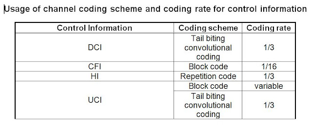
Channel Coding
Channel coding makes the bits resilient to the channel attenuation. Although this results in reduction of the data rate, it is essential to combat the attenuation.
The
bit sequence input for a given code block to channel coding is denoted by c0,
c1, c2, ....... cK-1, where K
is the number of bits to encode. After encoding the bits are denoted by d(i)0,
d(i)1, d(i)2, d(i)3,
................. , d(i)D-1, where D is the number of encoded bits per
output stream and i indexes the
encoder output stream. The relation between cK and d(i)K
and between K and D is dependent on the channel coding
scheme.
The
following channel coding schemes can be applied to TrCHs:
- tail biting convolutional coding;
- turbo coding.
The
values of D in connection with each
coding scheme:
- tail biting convolutional coding with
rate 1/3: D = K;
- turbo coding with rate 1/3: D = K
+ 4.
The
range for the output stream index i
is 0, 1 and 2 for both coding schemes.
Rate Matching and Interleaving
The 3 coded streams from the channel coding are subject to rate matching to match the bit rate of the transport channel.
The rate matching for channel coded transport channels is defined per coded block in 36.212 and consists of interleaving three information bit streams dk(0), dk(1) and dk(2), followed by the collection of bits and the generation of a circular buffer, as shown in figure below. The circular buffer based rate matching provides a simple method of generating puncturing patterns with good performance.
For the next stage of processing, go to the post on Physical Channel Processing.


